A. Todd-Pokropek
University College London
INSERM U494 Paris
The installation of PACS systems in many hospitals, which is proceeding rapidly, depends on the ability to capture radiographic (and other) images digitally. While this presents no problem in CT, MR and Nuclear Medicine, and while there are still some technical problems in angiography, fluoroscopy and even ultrasound, the major task has been the capture of conventional x-ray images in a satisfactory manner. In this area the use of photostimulable (CR) plates has been dominant, although digitisation of films particularly of old films has also been used. The purpose of this paper is to discuss the capture process, and to look at alternative technologies which might replace the use of CR plates, an area which is generally called Digital Radiology or DR.
How does a CR plate work? The basic idea initially developed by Kodak, but exploited for a long time by Fuji, was to use a thin layer of some material (normally an alkaline halide doped with a rare earth, such as CaF:Eu, KBrxCl1-x:Eu etc) where traps exist to catch electrons (or holes) released as a result of irradiation by x-rays [1]. These ‘traps’ essentially retain energy in a metastable state such that after irradiation by x-rays, the plate may then be irradiated by light and the traps ‘liberated’, that is energy is released at a very specific wavelength corresponding to the energy level of the trap. Thus the latent image is captured by scanning the plate normally with a laser and recording then light emitted by a photomultiplier, converting it to a digital image. The key features of this process are that the signal released is essentially linear with respect to intensity of x-rays (unlike film), the latent image can be sampled by using a low intensity read cycle, and the material is reusable after a high intensity erase cycle to remove completely the latent image. The resolution of the system depends on the spot size of the laser, the thickness (and type) of the photostimulable material, and details of the supporting material (base plate). The sensitivity of the process also depends on the thickness and type of material, the read time, and thus determines the signal to noise ratio in the final image.
What therefore would one like to improve with respect to this process? It would certainly be desirable to improve either the resolution or the sensitivity of the plate. Secondly it would be nice to be able to observe the image while (or very shortly after) the image is acquired, while the patient is still in place. If this process also enabled dynamic acquisition of images, such as fluoroscopy, this would also be useful. Thus the objective of a DR system is to devise an alternative for CR and possible also an alternative for conventional fluoroscopy/ angiography type systems. There are therefore a whole range of DR systems ranging from flat plate (FP) imagers, to sets of CCD arrays coupled to scintillating screen, to large x-ray sensitive video cameras. None of the schemes is particularly original (see for example [2]), but the increasing interest of the topic is that the original prototypes are now approaching real commercial production.
Two specific and different approaches have been developed: direct and indirect. The first aims to convert directly energy from the absorption of x-rays to an electrical signal; the later aims to convert x-ray energy to light (for example) which is then converted to an electrical signal in a second process using a photosensitive detector. It should be noted that other indirect processes can be imagined not involving light.Flat Plate (FP) Digital Radiology (DR) Devices.
It has been known for many years that a latent image from x-rays can be deposited or generated from a sheet of material such as amorphous Silicon (a-Si) or amorphous Selenium (a-Se). The breakthrough in the design of such detectors was the coupling of the x-ray sensitive layer to a read-out layer, for example an active matrix of thin film transistors (TFTs). The resolution of the system is effectively determined by the size of the pixel, that is the area of the TFT read-out cell. The sensitivity of the device is primarily determined by the thickness and density of the x-ray sensitive layer. Nevertheless, other factor do influence performance, for example the fill factor (what percentage of the area of the detector is in fact employed), and the nature of overlying and underlying material, for example influencing scatter. Since the TFT layer requires lines to each pixel, the technology is dependent on the ability to produce very fine and accurate thin film layers where some error rate (bad pixels) is inevitable. Typical pixel sizes are comparable for both CR and DR and of the order of 50-200 microns.
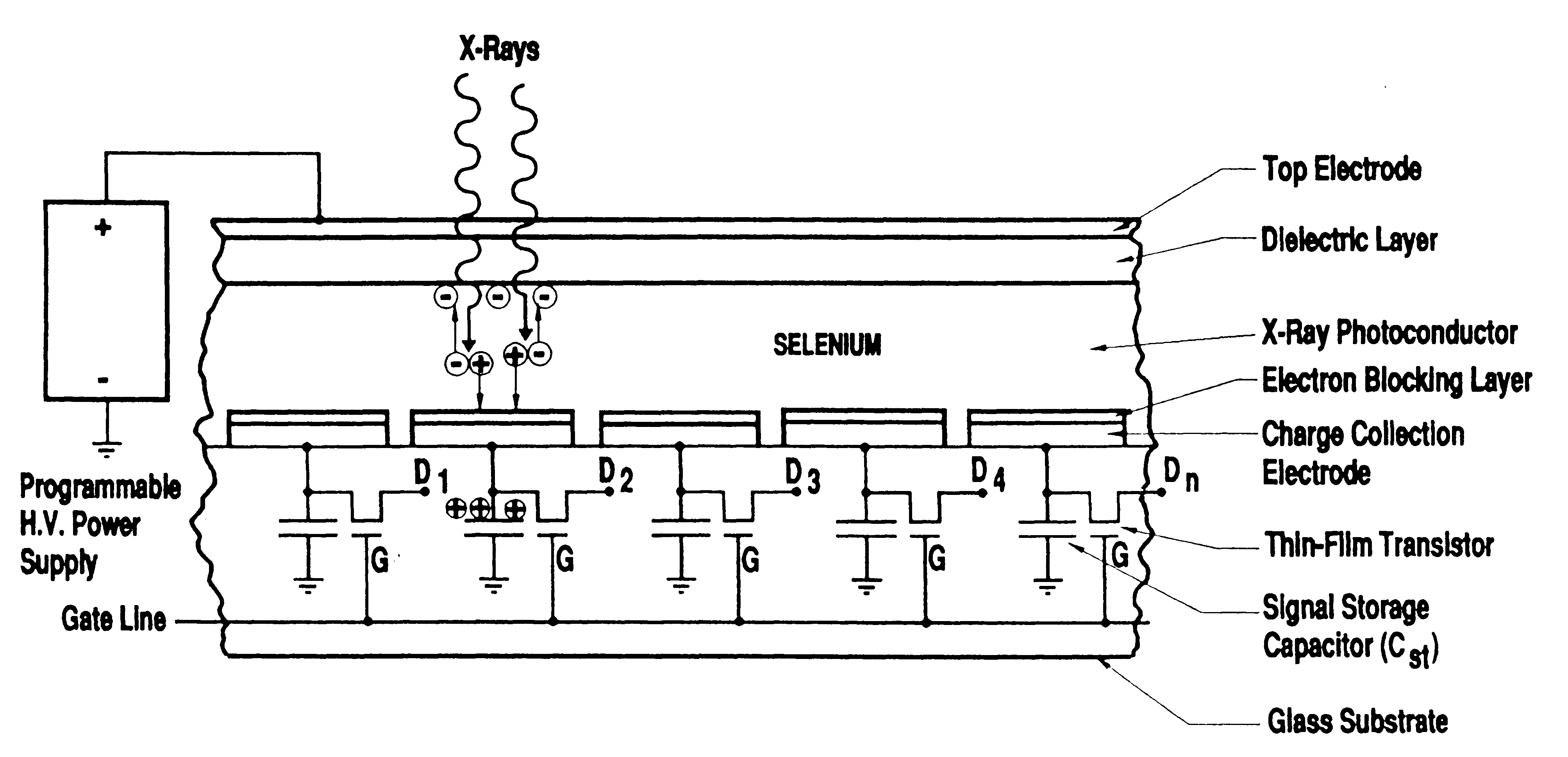
There are therefore two distinct types of DR plates. The first, as proposed by L.E. Antonuk and others [3], uses an amorphous Silicon plate as indicated in Figs 1 and 2, where the x-ray creates a scintillation, which is then detected, whereas the alternative is that as proposed by D.L. Lee and others [4] using an amorphous Selenium sheet, where the x-ray is converted directly to charge, which is then detected, as illustrated in Fig 3.
One clear difference exists between so called DR and CR. The
CR plate is removed and ‘developed’ in a separate unit. The DR detector is connected
by a cable to the associated electronics and need not be moved/removed. Therefore
a possible disadvantage of the DR system is for mobile use until suitable networks
have been established, or sufficient local processing and storage facilities
for the mobile use of the DR detector are available. While technically feasible,
the use of DR for mobile use is
probably currently
uneconomical.
Fig 1. Example of an indirect (a-Si) type plate with a scintillator producing light then detected by photodiode layer, with acknowledgement to [5]
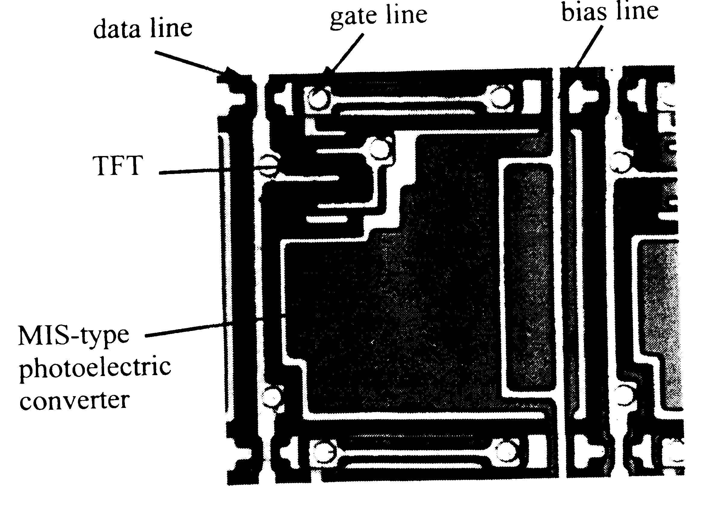
Fig 2 Microphotograph of a typical pixel with acknowledgement to [5]
Fig 3. Example of the design of a direct detector (a-Se) type of system with acknowledgement to [4]
Table 1 Some Commercial systems
|
Some manu-facturers |
Type of system |
Some characteristics |
|
Canon |
Silicon |
2688x2688 160micron 3.1 lp/mm |
|
Cares Built |
CCD |
7kx7k, 7 lp/mm 17”x17” |
|
Fuji |
CR |
5 lp/mm upto 10 lp/mm |
|
GE |
Silicon |
41x41cm 3-5 lp/mm |
|
Kodak |
Gd2O2S:Tb (GOS) |
19x24cm |
|
Konica |
CR |
As Fuji |
|
OldDelft |
CCD |
? |
|
Philips |
Silicon Selenium |
3.5 lp/mm |
|
Schick |
CMOS |
Upto 18x24 cm 40 micron pixel |
|
Siemens |
Silicon |
3.5 lp/mm |
|
Sterling |
Selenium |
3.9 lp/mm 139 micron pixel |
|
Swissray |
CCD |
3 lp/mm 2500x2500 14”x17” |
|
Thomson |
Silicon |
43x43cm 2981x3011 143 micon pixel 3.5 lp/mm |
|
Toshiba |
Selenium |
Similar to Sterling |
|
Trex Medical |
Silicon CMOS |
Similar to Siemens |
|
Varian |
Silicon LAST |
9”x9” fluoroscopy |
This table based on data collected by a colleague, Guy Frija [6] shows the number and variety of commercial systems that are becoming available for digital radiology, plus some indication of possible performance. Only one DR system has at present FDA approval, that is the system proposed by Sterling (original patent [7]). However one expects many of the others to obtain approval shortly. In particular the systems proposed by Siemens, Philips, and Thompson are all based on a similar design and appear to have similar performance. One suspects that number of the parameters of the design have been chosen for example the matrix size of the resulting image have been chosen so as to match the current performance of CR plates. However, it is quite possible that with the change and improvement of technology, these characteristics will change and improve.
An additional important characteristic of such detectors is their size, for example how they are mounted. A number of them are quite large and essentially serve as devices for direct capture of chest x-ray, and are therefore wall mounted. However, the ‘ideal design of a DR detector is aimed towards a thin plate which can be used in the same manner as a conventional film screen or CR cassette.
In conclusion, these systems are now entering proper clinical evaluation [8] and one awaits additional developments and widespread use with considerable interest.
1. Nanto H, Sato T, Shinkawa T, Miyazaki M, Imai A, Kusano E, Kinbara A, Nasu S and Douguchi Y, New photostimulable phosphor materials ofr imaging plate of computed radiography, in SPIE Physics of Medical Imaging Vol 3336 (1998) 564-571
2. John JE New methods of imaging in diagnostic radiology. Br. J. Radiol. (1976) 49:745-764.
3. Antonuk LE, Yorkston J, Huang W, Boudry J, Morton EJ, Longo MJ and Street RA, Radiation response characteristics of amorphous silicon arrays for megavoltage radiotherapy imaging, IEEE Trans Nucl.Science 39 (1992) 1069-1073
4. Lee DL,Cheung LK and Jeromin LS, A new digital detector for projection radiography SPIE Physics of Medical Imaging Vol 2432 (1995) 237-249
5. Kameshima T, Kaifu N, Takami E, Morishita M and Yamazaki T, Novel large area MIS-type x-ray image sensor for digital radiolgraphy. SPIE Physics of Medical Imaging Vol 3336 (1998) 453 462
6. Frija G. Digital radiography: Questions and Answers, in CAR’98, Computer Assisted Radiology and Surgery. Excerpta Medica International Congress Series, 1998.
7. Cannella V, Yaniv Z and Johnson R, X-ray image scanner and method. US Patent #4,672,454, issued June 1987, filed December 1984.
8. Shaber GS, Lee DL, Bell J, Powell G and Maidment ADA, Cinical evaluation of a full field digital projection radiograpy detector. SPIE Physics of Medical Imaging Vol 3336 (1998) 463-469.
Oral presentation at EuroPACS'98, Barcelona, Spain